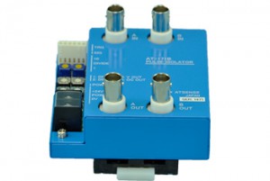
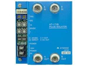
■ A pulse isolator unit for pulse shaping of the pulse input signal using a comparator, isolation with a photocoupler, frequency division, and then pulse output.
■ The trigger level is adjustable to any desired value between 0 and 10V.
■ A possible frequency division ratio over a range 1 to 99.
■ 2 channels built in to the same device.
■ A casing which can be mounted on a DIN rail.
■ For the input, combined use of a nylon connector with sensor power supply and a BNC connector, and for the output, connection with a BNC connector.
| Input signal | |
|---|---|
| Number of channels | 2ch |
| Signal level | ±30V |
| Trigger level | 0 to Approx. 10V Variable with the “TRG” VR on the substrate |
| Minimum trigger input level | 300mVp-p |
| Input resistance | Approx. 1MΩ (for a range of 0 to +12V) |
| Input frequency | 0 to 200kHz |
| Sensor power supply | DC5V 30mA max |
| Output signal (output switching with substrate switches) | |
| Voltage signal | |
| Output logic | Input signal “H” ⇒Voltage output “H” |
| Output level | “L” level voltage signal of 1.5V or less “H” level Voltage signal of 3.5V or greater |
| Output current | 20mA max |
| Open collector signal | |
| Output logic | Input signal “H” ⇒Open collector ON |
| Output rating | 30V 100mA max |
| Signal LED | Red: indicates the output state |
| Frequency division | |
| Frequency division ratio | Switching from 1 to 99 with a rotary switch on the substrate |
| Frequency division/direct switching | Switching with a switch on the substrate |
| General specification | |
| Insulation range | Input/output/supplied power (no insulation between channels A and B) /casing |
| Signal insulation | Insulation with a photocoupler |
| Supplied power sources | DC24V ±20% 100mA max |
| Power supply LED | Yellow: indicates the power supply is ON |
| Operating temperature and humidity range | 0 to 40ºC/85%RH or less (with no condensation) |