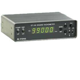
If you want to measure rotation speed and with good accuracy, the ET-100 Engine Tachometer, with its pulse and analog output, can respond to this need.
Packed with all the capabilities of an engine tachometer, but can of course still be used as a tachometer for general FV conversion.
Conveniently built-in functions for engine revolution measuring
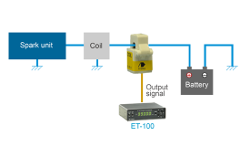
Apart from the ignition pulse detector (sold separately by our company), it is also compatible with various other sensors including gear sensors, proximity sensors, and photoelectric sensors.
Built-in high-speed response for F/V conversion output, pulse output, and USB output

■ Resolution per revolution
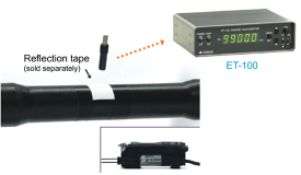
Measurements can be taken whether using both a piece of reflection tape to mark each revolution, or if there are 60 gear teeth.
Setting the number of pulses will display r/min data automatically.
■ Measurement data
As well as a digital display, analog (FV output) and USB data are also output.
Because USB data is output every 0.1s on a digital display, there is no lag between the display data and data on the PC.
■ Pulse output
The signal which is input undergoes wave shaping before output.
And simultaneously, a pulse is output once every revolution, or a half-frequency signal is output.
■ Power supply
The unit is driven by 9 to 32V DC. And an AC adaptor is supplied as an accessory.
■ Accuracy
Display accuracy of ±100ppm±1digit. High accuracy analog output (FV output) of ±0.1%F.S
■ Wide variety of functions
The input selects the AC/DC coupling, and many functions, including a moving average and pulse response delay, are then available as standard for improving the measurement.
| Display | |
|---|---|
| Display method | 7 SEG LED, character height 10mm, 5 digits, green |
| Display items | Rotational speed |
| Display range | 0 to 99999r/min, and “OVER” displayed if 100000 or more |
| Display refresh time | 0.1 to 1.0(s) |
| Zero display | Leading zero suppression |
| Accuracy | ±100ppm±1digit |
| Trigger display | SIG green blinking LED, continuously lit for high-speed pulse input |
| Input | |
| Number of inputs | 1 input (BNC connector and 3-pole connector are internally common) |
| Input signal format | Voltage pulse (voltage resistance ±30V) |
| Input coupling | DC/AC |
| Trigger level | ± 0.2V to ±10.0V |
| Hysteresis | 0.2V/2V |
| Pull-up | OFF/Pulled up to 12V by 10kΩ |
| Trigger direction | Rising/Falling |
| Frequency range | 0.1Hz to 9.8kHz (depending on the wave shaping pulse width) |
| Sensor power supply | 12V (100mA max) |
| Input resistance | Approx. 100kΩ |
| Number of pulses per revolution | 0.5 to 360.0p/rev |
| Pulse output | |
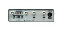
| Number of outputs | 2 outputs (BNC connector) |
| Output items | P OUT: wave shaping output P OUT2: half-frequency division output/1 pulse output per revolution |
| Signal level | 0-5V logic signal, 10mA max |
| Output logic | Normal or Reverse |
| Analog output | |
| Number of outputs | 1 output (BNC connector) |
| Output items | Rotational speed |
| Output range | 0 to +10V |
| Accuracy | ±0.1%F.S. |
| Refresh time | 1ms per each pulse signal input |
| Allowable load resistance | 10kΩ |
| Data output | |
| Connector | USB mini B |
| Refresh time | Synchronized with display refresh time |
| Output content | Rotational speed display value |
| * Please contact us for details about the software on the PC side. | |
| General specification | |
| Insulation | Power supply input/signal input/analog output and pulse output, USB |
| Power supply | 9V to 32V, 5W (max) |
| Connector | Rear panel φ 5.5×2.1 standard DC jack (center positive) |
| Protection functions | Reverse polarity connection protection |
| Power switch | Front panel slide switch |
| Product case | Aluminum case, anodizing treatment |
| External dimensions | W: 140 H: 40 D: 100 (excluding projecting parts) |
| Weight | Approx. 400g |
| Operating temperature range | 0 to 40ºC / 85%RH or less (with no condensation) |
| Accessories | Rubber feet (4), AC adaptor (1), DC plug cable (1) |

Digital display of number of engine revolutions.

Rotation detection with a commercially available photoelectric sensor.