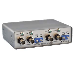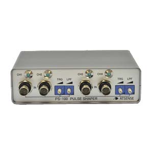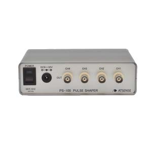


By inputting the output from the CLP-10 Clamp-on AC Pickup to the PS-100, variations in the drive current, from the start of ignition (IGN) charging to discharge, and from the start to end of injection (INJ), can be converted into a 0-5V pulse signal.
The trigger level for the 4-channel input can be set for each of the channels 1, 2, and the channels 3, 4.
The trigger level is switched between 4 steps.

■ 4-channel input
■ The analog signal from the CLP-10 Clamp on AC Pickup is converted to a digital signal and output
■ The trigger level can be set in 4 steps
■ A low pass filter provides noise reduction
■The trigger level and low pass filter can be set for each of channels 1, 2 and channels 3, 4.The white line is the wave shaped output from the PS-100.

The white line is the wave shaped output from the PS-100.

| Input/output connector | BNC |
| Number of channels | 4ch |
| Detector | CLP-10 Clamp on AC Pickup |
| Input circuit adjustment |
1) TRG (trigger level) switch: 4-step switching±0.5, ±1V, ±2V, ±5V |
| Output circuit | For both TTL input and contact input (external pull-up voltage maximum 30V) |
| Output rating | H(5V) level 3.5V or more (4mA)、L(0V) level 1.5V or less (10mA) |
| Output logic | Output H level during ignition and injection drive current energizing |
| Indicator | Lights at output H level: Green element green light LED |
| Response speed | Within 3μs after trigger level is exceeded at the input terminal |
| Signal insulation | None (input/output ground common) |
| Power input range | DC9 to 32V (5W), reverse polarity connection prevention (automatic reset), signal insulation |
| Power supply connector | f5.5×2.1 standard DC jack (center + polarity) |
| Body case | Aluminum case, anodizing treatment |
| External dimensions & weight | W:140 H:40 D:100 (excluding projecting parts), weight: Approx. 400g |
| Operating temperature range | -10°C to 50°C (no condensation) |
| Accessories | AC adaptor × 1, DC plug cable × 1, adhesive rubber foot × 4 |