Reversible pulse counter
■ Maximum input frequency 2MHz (for single-phase), 500kHz for two-phase input
■ High-speed 0.5ms response for analog output and digital output
■ CAN output supported
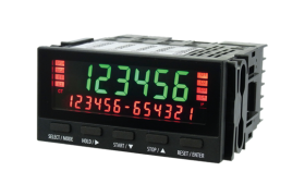
■ 6-digit and 13-digit, two-level, high brightness LCD display (red and green)
High-precision, highly-functional digital panel meter with built-in counter and angle measurement function
The model configuration for this instrument is as shown in the figure below.
The model is left-justified when option “No” was selected.
Multiple options cannot be chosen from options in the same group.
Two different types can be selected out of digital output, contact output, and communication.

| Model | URC-200 | |
|---|---|---|
| Name | Reversible pulse counter | |
| Arithmetic | ||
| Input operations | A/AB (reversible) | |
| Operation key | 5 points Separate function at measurement/setting | |
| Memory | Memory element | Non-volatile memory |
| Memory content | Setting value and count value | |
| Display | ||
| Display | LCD negative, backlight | |
| Main display | Display items | Count value |
| Display color, character height, number of digits | Switching between red and green backlight, 14.2mm, 6 digits + polarity (-) | |
| Sub-display | Display items | Count value/Comparator setting value/OFF |
| Display color, character height, number of digits | Switching between red and green backlight, 6.5mm, 13 digits + polarity (-) at 2 points | |
| Status display | Display color | Switching between red and green backlight |
| Signal input (sensor input) | ||
| Number of inputs | 2 inputs | |
| Types of input signal (CH) | Single-phase (2ch) / UP/DOWN (1ch) / A/B 2-phase signal (1ch) switching | |
| Maximum input frequency | Single-phase, UP/DOWN signal | 2MHz |
| A/B 2-phase signal | 500kHz | |
| Signal input (sensor input) (0) General purpose | ||
| Input level | AC (zero-cross) signal Signal A |
±200mV to ±30V, LPF switching |
| Logic signal | H level 3.9V or more, L level 1V or less (voltage resistance ±30V) | |
| Others | Pull-up/pull-down switching | |
| Power supply for sensor | Voltage and maximum current | DC12V±10%, 100mA |
| External control input | Number of points | 2 inputs |
| Signal type | Contact/TTL (minimum pulse width 5ms) | |
| Items | Reset/Hold switching | |
| Signal input (sensor input) (L) line | ||
| Input level | TTL (logic signal) | H level 3.9V or more, L level 1V or less (maximum ±30V) |
| Line driver signal | Differential signal compliant with RS-422 (485) (maximum ±7V) | |
| Power supply for sensor | Voltage and maximum current | DC5V±10%, 200mA |
| Analog output | ||
| Refresh time | 0.5ms | |
| D/A conversion | 16-bit | |
| Analog output (V) General purpose (1CH) | ||
| Number of outputs | 1 output | |
| Output items | Count value | |
| Output range | Voltage output range | ±10/0-10/0-5/1-5 V (load of 4.7kΩ or more) |
| Current output range | 4-20mA (load of 560Ω or less) | |
| Accuracy | Voltage output ±0.1%F.S. or less/current output ±0.2% F .S. or less (23ºC)/temperature variation ±200ppm/ºC or less | |
| Analog output (W) Voltage (2CH) | ||
| Number of outputs | 2 outputs | |
| Output items | Count value | |
| Output range | Voltage output range | ±10V (load of 4 .7kΩ or more) |
| Accuracy | Voltage output ±0.1%F.S. or less (23ºC)/temperature variation ±200ppm/ºC or less | |
| Contact output (C) contact output (photo MOS relay), (O) contact output (open collector) | ||
| Number of outputs | 4 outputs | |
| Refresh time | 0.5ms | |
| Output items | Comparator | |
| Output circuit | (C) Photo MOS relay | Maximum load voltage (peak AC/DC) 350V, continuous load current (peak AC/DC) 80mA, output ON resistance 35Ω (typical) |
| (O) Open collector | NPN open collector, maximum load voltage 30V, maximum load current | |
| 15mA | ||
| Communication (4) RS-485 (2) RS-232 (U) USB | ||
| Communication format | Serial communication | (4) RS-485/(2) RS-232/(U) USB |
| Communication speed | 9.6k/19.2k/38.4k bps | |
| Data length | 7/8 bit | |
| Parity bit | Null/even/odd | |
| Stop bit | 1/2 bit | |
| Character code | ASCII | |
| Digital output | ||
| Output items | Count value | |
| Refresh time | Analog synchronization/display synchronization switching | |
| Digital output (T) BCD output (TTL), (P) BCD output (open collector) | ||
| Number of output digits | 6 digits + polarity | |
| Output circuit | (T) TTL | Output voltage 0-5V (output current ± 100mA, but ± 4mA/ch) |
| (P) Open collector | NPN voltage 30V, maximum load current | |
| 20mA/ch | ||
| Digital output (N) CAN | ||
| Output circuit | CAN2.0B compliance | High-Speed CAN (ISO11898-2) |
| Communication speed | 1Mbps/500kbps/250kbps/125kbps | |
| Data format | Little endian/Big endian | |
| ID length | Standard 11bit/Extended 29bit | |
| Data format | Signed long (4 bytes) | |
| Output refresh time | Digital output refresh time/1/2/5/10ms | |
| General specification | ||
| Supplied power sources | (A) Power supply (AC) | AC100 to 240V ±10% (50/60Hz), |
| (100V, 18VA or less, 240V, 24VA or less) | ||
| (D) Power supply (DC) | DC12 to 24V ±10% (10W or less) | |
| Electrical insulation | Insulation range | Sensor input – analog output – contact output – communication and digital output – supplied power sources |
| Protective structure | Front panel IP66 | |
| Operating temperature and humidity range | 0 to 50℃, 85%RH or less (with no condensation) | |
| External dimensions, Weight | W: 96 H: 48 D: 100 (D: 93 inside part) | |
| Approx. 230g (when equipped with all options) | ||
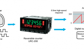
Rotation angle display and output using a reversible pulse counter (URC-200) for the two-phase signal from a rotary encoder.